Introduction of the ARGB Solution
2025/09/26
Introduction
ARGB (Addressable-RGB) is a popular type of LED lighting widely used in illumination, decoration, and electronic projects. The 'addressable' part refers to the ability to control each LED's color and brightness individually through an integrated circuit (IC) embedded in or connected to each LED, allowing point-to-point programming to produce more diverse light effects.
ARGB LEDs are typically connected in a daisy-chain configuration, with each LED module containing a built-in control chip. The built-in IC transmits color and brightness instructions through digital signals. Common models include: WS2812B, WS2813, SK6812, SK9822, APA102, which can be divided into those with and without breakpoint continuation or with and without a clock channel. Addressable RGB LEDs with breakpoint continuation feature have a data channel and a backup data channel, allowing the signal to still be transmitted to subsequent ICs if only one IC fails. Addressable RGB LEDs with a clock channel feature have a data channel and a clock channel, enabling higher data transmission speeds and more reliable signals.
The following provides an example of using Realtek Bluetooth SOC to achieve ARGB lighting effects control, using WS2812B as an example.
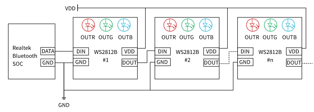
WS2812B Daisy-Chain Connection Diagram
ARGB Communication Method
Using WS2812B as an example, ARGB lights utilize a Unipolar Return-to-Zero (RZ) communication method. The input patterns include '0' code, '1' code, and 'RESET' code, as shown in the following figure. The timing for the three types is listed in table below.
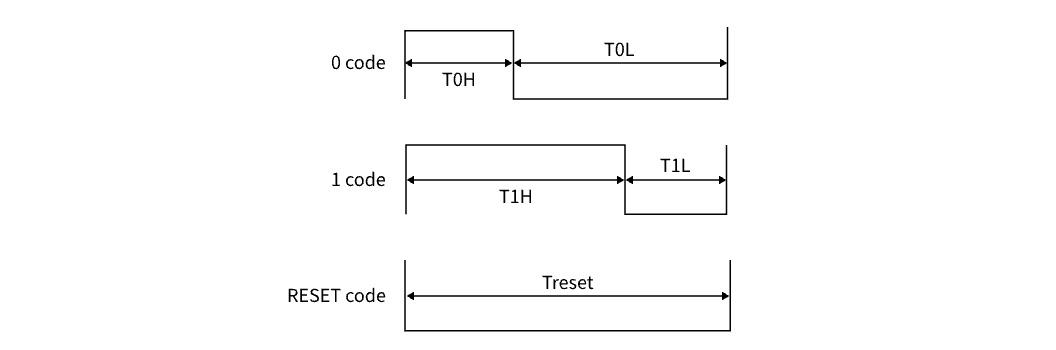
Input Code Type
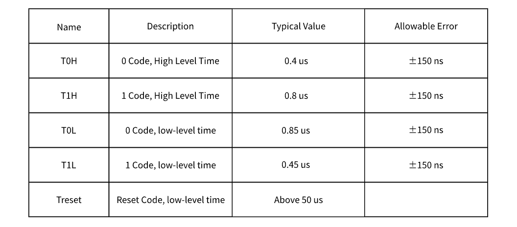
Code Type Timing (TH + TL = 1.25 us ± 600ns)
After power-on reset, the WS2812B receives data transmitted from the Realtek Bluetooth SOC at the DIN terminal. The first 24-bit data sent is extracted by the first WS2812B and sent to the internal data latch. The remaining data is output through the DOUT terminal to the next cascaded WS2812B after internal reshaping processing. With each WS2812B transmission, the data is reduced by 24 bits, as shown in the following figure.
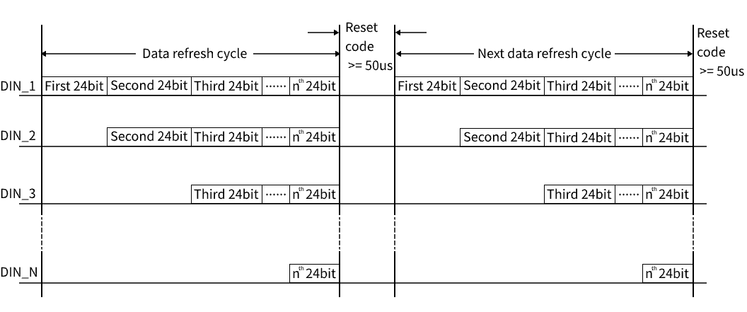
ARGB Data Transmission
Where DIN_1 is the data sent from the Realtek Bluetooth SOC, and DIN_2, DIN_3, and DIN_n are the data automatically reshaped and forwarded by the cascade circuit.
The 24-bit data structure is shown in the following figure, with the high bit sent first in the order of GRB.
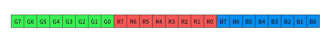
24-Bit Data Structure
Once the WS2812B receives the 24-bit data, it sends it to the internal data latch and forwards the remaining data through the DOUT terminal. It then waits for the 'RESET' code at the DIN terminal. Upon receiving the 'RESET' code, all cascaded WS2812Bs synchronously generate signals with different duty cycles at the OUTR, OUTG, and OUTB terminals based on the received 24-bit data. Before the next 'RESET' code is received, the OUTR, OUTG, and OUTB terminals maintain their original output. Upon receiving the next 'RESET' code, the output at the OUTR, OUTG, and OUTB terminals will be refreshed, as shown in the following figure.
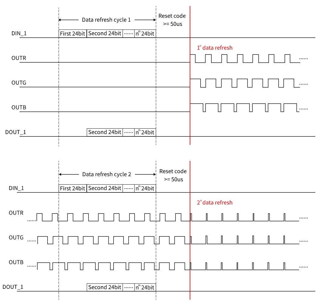
ARGB Communication Method Diagram
Use Timer + DMA to control ARGB
Connect the PWM end of the Realtek Bluetooth SOC to the DIN end of the ARGB, configure the Timer and DMA to generate a PWM signal with the corresponding frequency and duty cycle, so that its output matches the timing pattern to control the ARGB.
Taking ARGB with WS2812B as an example, the Timer and DMA configuration is as follows:
1. Timer Configuration:
Set the Timer to produce a PWM signal with a frequency of 800kHz, where a PWM signal with a 75% duty cycle simulates a '1 code', and a PWM signal with a 25% duty cycle simulates a '0 code'.
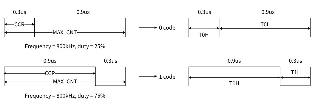
PWM Signal Simulating ARGB Input Code Type
2. DMA Configuration:
Configure the DMA channel to transfer data from the buffer storing color data to the Timer's CCR register. DMA operations can reduce CPU load and ensure data transmission accuracy and timing correctness.
During data transmission, ensure continuous updating of LED color data, avoiding idle times exceeding 50us. If a reset occurs, data transmission must restart to maintain continuity and correct display effects.
Use SPI + DMA to control ARGB
The SPI bus only transmits data during transmission, and its high transmission speed is suitable for simulating ARGB communication methods. Connect the SPI MOSI end of the Realtek Bluetooth SOC to the DIN end of the ARGB, configure the SPI and DMA to output a pattern that matches the timing to control the ARGB.
Taking WS2812B as an example for ARGB, the SPI and DMA configuration is as follows:
1. SPI Configuration:
The SPI clock of Realtek Bluetooth SOC is generally 40MHz. By dividing the SPI clock by four, the SPI clock cycle is 0.1us, indicating that the transmission time for one data bit is 0.1us. The SPI data frame size is set to 12. Sending data '0xFF8' simulates '1 code', and sending data '0xE00' simulates '0 code'.
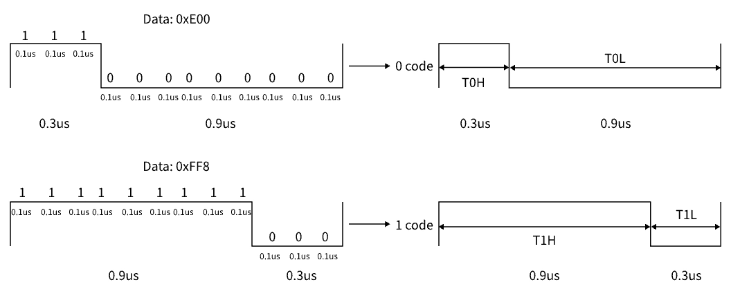
SPI Data Simulating ARGB Input Code Pattern
2. DMA Configuration:
Configure the DMA channel to transfer data from the buffer storing color data to the SPI TX FIFO register. DMA operation can alleviate CPU load and ensure the precision and timing accuracy of data transmission.
During data transmission, ensure continuous updating of LED color data to avoid exceeding 50us of idle time. If a reset occurs, data transmission needs to restart to maintain consistency and correct display effects.
SW Implementation
The RTL87x3D and RTL87x3E all support implementing ARGB lighting control using SPI single-wire mode. To meet varying application needs, SPI communication provides multiple driving modes, including polling mode, interrupt mode, and DMA mode. For detailed implementation samples and code, please refer to the document:
https://docs.realmcu.com/sdk/rtl87x3d/common/en/latest/text/Samples/IO/spi_master_rgb_write.html.
The RTL87x2G supports implementing ARGB lighting control using ENHTIM + DMA and SPI single-wire mode. It provides an exclusive sample for implementing the ENHTIM + DMA option. For detailed implementation samples and code, please refer to the document:


 苏公网安备32059002006558号